A project of this scope requires tapping numerous diverse technologies including electrical,
mechanical and software design.
In addition, there are opportunities to explore numerous techniques for infrastructure build.
Here is a short summary of the technologies I ended up using to integrate the display into
an automated operation that I could simply turn on and let it run without further intervention.
WEB/INTERNET
- Internet Domain Name
- Porkbun.com provided us the Brinkman.Christmas internet domain name.
- Internet Web Site
- You're viewing information about the display on our internet web site,
also hosted on Porkbun.com web servers.
- Dynamic Domain Name
- Live information for the Display is not provided by the Internet web site;
it is provided by the Master unit at our house that actually runs the Display in real-time.
In order to seamlessly provide this capability a Dynamic Domain Name Service (DDNS)
was needed to direct users to the address Live.Brinkman.Christmas.
DuckDNS provided the free DDNS service.
- Local Web Site
- Live information about the Display is provided by the local web site,
an ESP826 microprocessor.
Information provided includes the FM 89.3 MHz radio frequency, the song list (showing the song
playing at the time), and weather information.
CONTROL
- Distributed Control
- Outdoor displays are large - some are several blocks long.
It quickly becomes impractical to run long wires to each light or string of lights.
As a result, control of the display is divided into smaller, locally controlled segments.
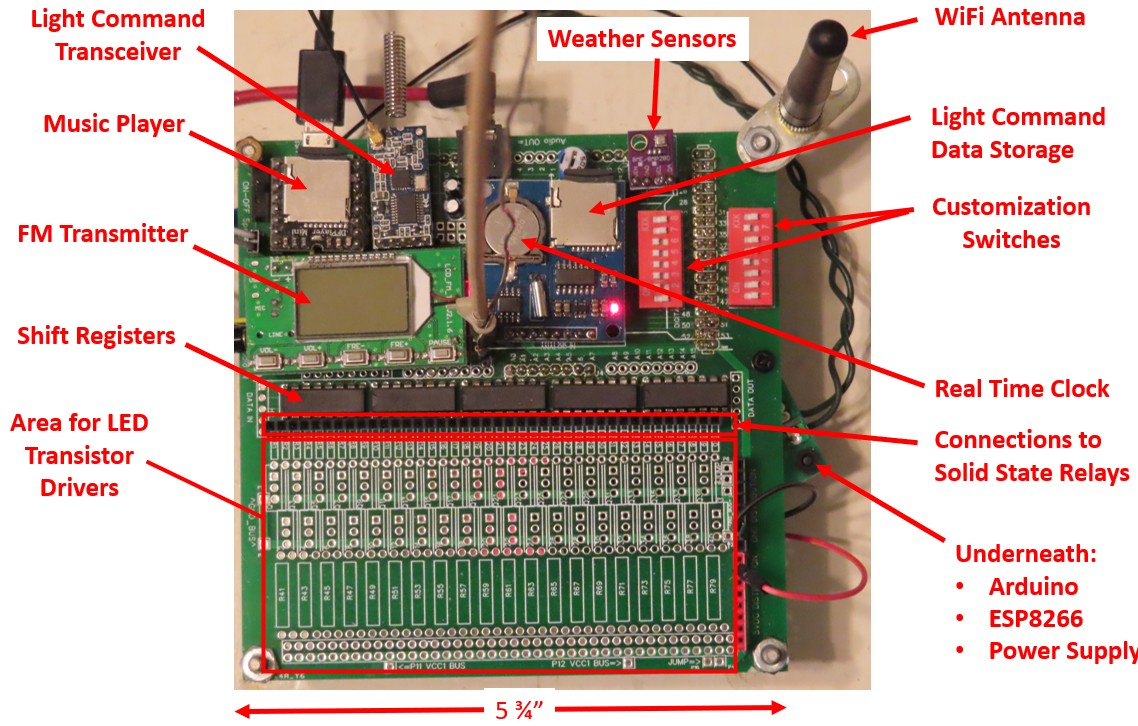
- Master Unit
- The Master unit controls everything in the Display.
It decides what to play, when to play it, then wirelessly commands all of the Slave units
to do their part of the show.
The Master unit has the Light Command script for all units, a wireless transceiver, the Music Player,
the FM Radio Transmitter, a Clock, and even a Weather Station.
- Slave Units
- Each local Slave unit operates at the direction of the Master unit.
Its instructions are received wirelessly from the Master unit.
It has an assigned subset of lights to control and turns them on/off as directed.
When asked, Slave units give a Health report to the Master unit.
The Slave units are identical to the Master unit except that only the wireless transceiver
is needed to receive its instructions.
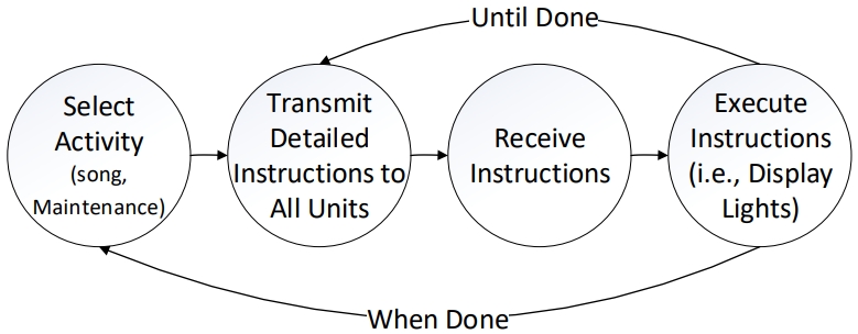
- State Machine
- The computers operate as "state" machines.
The computers stay in their current state until specific conditions are met before moving on to another state.
The technique helps keep the logic simple because there is a single focus for each state.
The Christmas display state machine is as follows:
- Light Sequence Commands
- I considered using commercially available products like Vixen and xLights to compose the
light sequence commands.
Complexity and usability issues caused me to develop a custom Excel spreadsheet-based light sequence
command tool that gives flexible control of up to 464 strings of lights plus twelve servos.
The process is a bit arduous, but allows complete freedom to control each of the individual circuits.
When the scripts are created or updated a Visual Basic macro generates the light sequence ommands
in less than a second.
The Commands are loaded onto a microSD card and placed in the File Storage card on the Master unit.
COMPONENTS
- Software
- Computer programs, or software, give the ability to take a generic computer and customize it
to function exactly as required to meet the needs of the application designer.
Following are the software tools that make this happen.
- Arduino C++ Language Reference
- Computer programs are written in a human-readable structured langage that can be
interpreted by machines to do what the programmer intended them to do.
Programs for the Christmas display are written in the C++ language.
- Arduino Integrated Development Environment (IDE)
- Before the program can actually be used by the computer it must be "compiled" into a language/format
that the computer can understand.
The Arduino IDE compiles and loads the program into the Christmas display computers.
- Christmas Display Program
- The Christmas display program that is loaded into the Master and Slave units is identical.
Each unit is assigned a Unit Number, which tells that unit which role(s) it plays in the Display.
- Playlist
- The Master unit opens a Playlist and an Announcement List that tell the Display which songs
and announcements to play.
When the lists are completed they start over at the beginning.
- Audio Files
- The music player contains "MP3" format audio files that are stored on a microSD
card and played when called for on the Playlist/Announcement list.
Audio files often require editing; in my case the free
Audacity application met all my needs.
- Light Files
- A microSD card contains Light Command files that tell the computer
what lights to turn on, and when.
In addition to lights, commands that cause servos to move up/down/left/right are contained in the file.
The light and servo commands are timed to match the music being played.
Up to 464 lights/light strings and 12 servos can be controlled by the Display.
Each time a light(s) needs to be turned on/off or a servo position changed the command for all
464 lights and 12 servos is transmitted, even if only one light changed.
- HyperText Markul Language (HTML)
- Web pages are written in a structured set of symbols and codes called HTML.
This web site is written in HTML, and the Live Songlist is written in HTML.
The HTML language permits organizing and formatting text, including images and videos,
and much more to give a professional looking result.
- Network Time Protocol (NTP)
- The Display needs to turn on at 5:30 and turn off at 11:00 each day.
The internet provides a service (NTP) that anybody can contact to get an accurate report of the current time.
When the processor turns on one of the first things it does is contact the NTP server to get the current time.
It then updates the local Real Time Clock (RTC - see below) to keep track of time from that point on.
NTP is consulted for a time update once per day to update the RTC just in case the RTC has drifted slightly.
- Electrical Hardware
- Software loaded into the computers tells the computers what to do; in turn, the computers
are attached to other hardware to receive information or to cause an action to be taken.
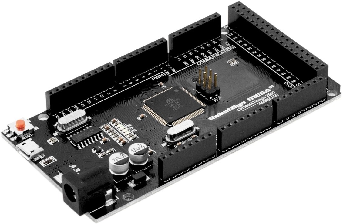
- Microprocessor
- All the Slave units, and the Master unit through 2018 were powered by Arduino Mega 2560 microprocessor computers.
The Mega is an 8 bit computer that has a 16 MHz processor and many digital and analog interfaces that make it easy to connect to other hardware.
In addition, standard interfaces minimize the effort required to get the hardware devices to talk to each other.
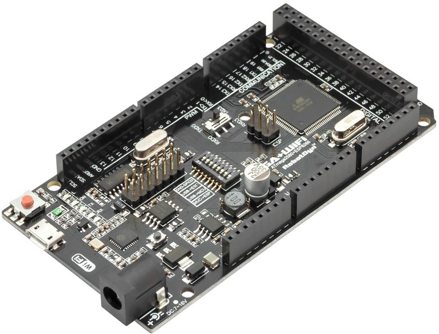
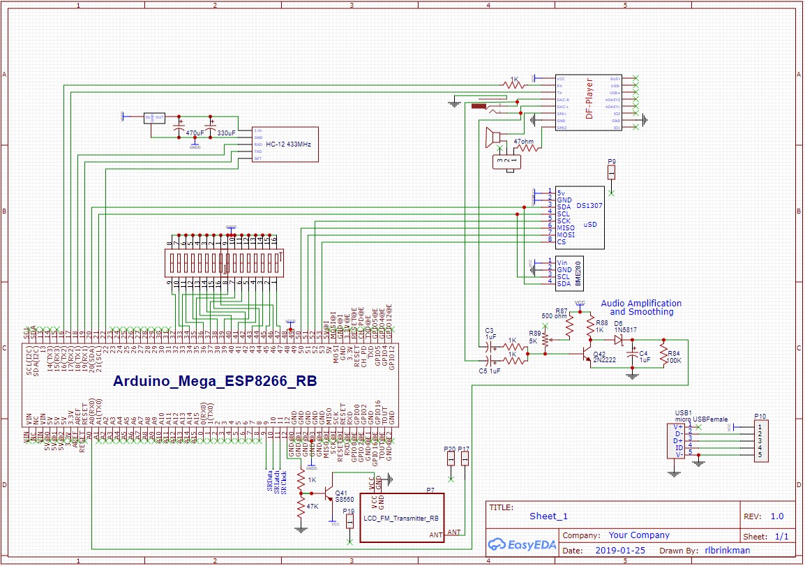
- Microprocessor + WiFi
- In 2019 the Master unit was upgraded to pair the Arduino Mega 2560 with an ESP8266
processor that has WiFi capability.
Both processors fit on the original card size - it's just a bit more crowded.
For the first time this permitted the status of the Display to be viewed and controlled via a web page.
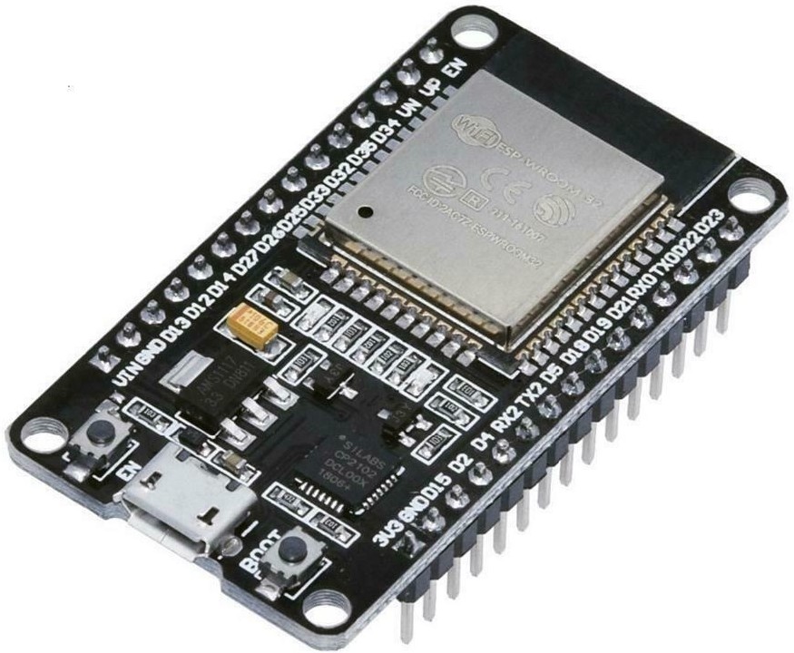
- Upraded Microcontroller + WiFi
- In 2020 the Master unit Arduino Mega 2560 + ESP8266 was going to have been replaced by an ESP32
microprocessor computer.
The ESP32 has two 32 bit processors that run at 240 MHz; the resulting performnce is about 200 times
faster than the Mega.
In addition to digital and analog interfaces, the ESP32 has built-in WiFi, Bluetooth, and a Real Time Clock (RTC).
Probably the nicest feature is that the ESP32 can be reprogrammed over WiFi, permitting
me to update the unit out in the yard while sitting at my desktop computer.
Unfortunately the ESP32 turned out to be a bit more tempermental than the Mega so I didn't succeed in
finishing the update.
Maybe next year.
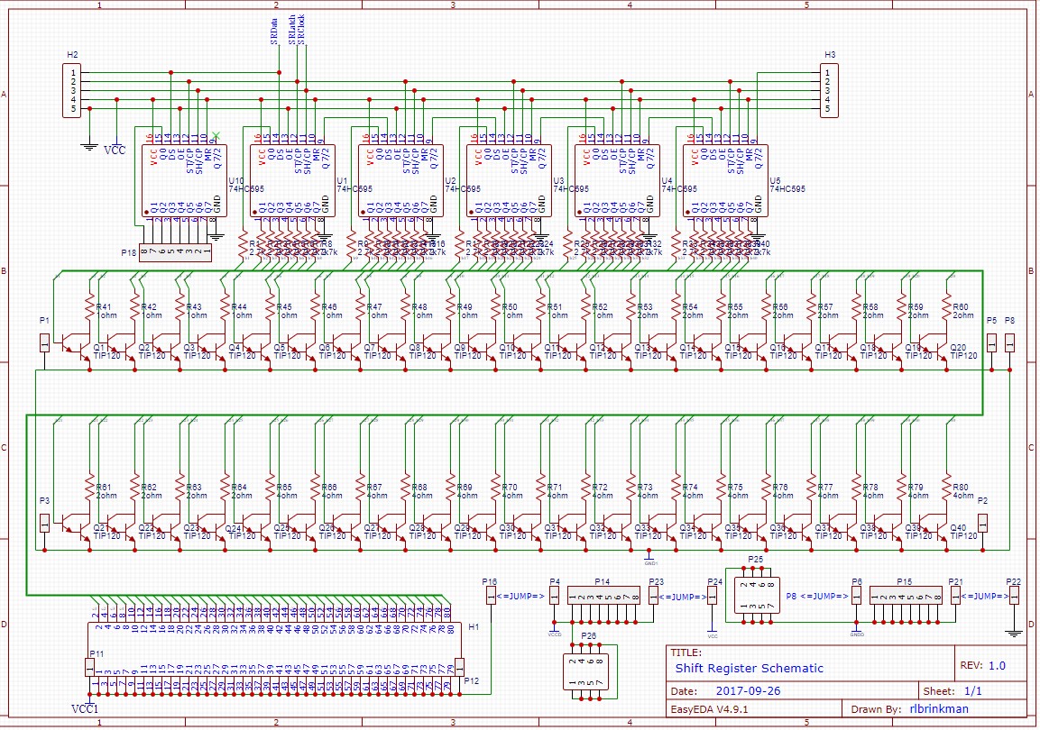
- Shift Registers
- The microprocessors are powerful, but they have a limited number of pins to output data.
Since we need to connect up to 464 light strings, we need a way to get the data out to 464 different places.
The microprocessor sends one bit at a time out to a series of 74HC5595 shift registers.
Each shift register holds 8 bits of data but can be strung together to hold as many bits as required.
Each bit is used to control a light string on or off depending on the value of its assigned bit.
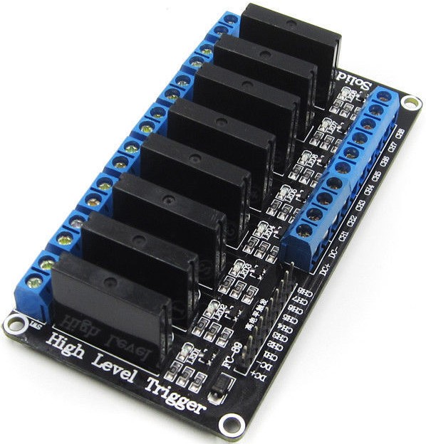
- Solid State Relays (SSRs)
- Microcontrollers operate at voltages between 3.3 - 5 VDC.
Many light strings operate at 110 VAC.
The job of the SSR is to accept a low voltage command from a shift register and activate a high voltage
light string.
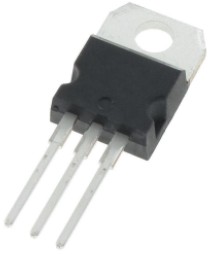
- Power Transistors
- Microcontrollers and shift registers can provide 20-40 mA current to LED light strings.
A typical LED light string requires about 340 mA.
The transistors connect to a shift register pin and provide the boost needed.
The transistors can drive a range of voltages from 5 to as high as 60 VDC if required.
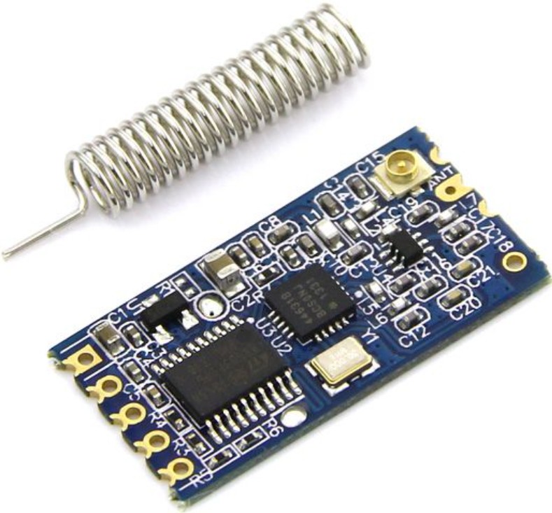
- Transceivers
- Each unit has a HC-12 transmitter/receiver (transceiver) that permits communication between the Master and Slave units.
The transceivers operate at a frequency of 433 MHz and have a range of a 1 Km.
Each set of light commands are broadcast by the Master unit to the Slave units in about 17 ms.
With plenty of room reserved for cushion, a new light command can be issued every 50 ms, or 20 times per second.
Slave units also use the transceivers to report their health back to the Master unit, permitting corrective
action to be taken if there is a problem.
- File Storage
- Light Commands and Playlists are stored in files contained on a MicroSD card.
In our case the microSD card reader and the Real time Clock (see next item) are combined on
a single Data Logger module.
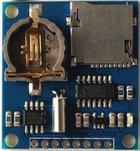

- Real Time Clock (RTC)
- The Display needs to turn on at 5:30 pm and turn off at 11:00 pm each day.
The RTC keeps track of time to make this possible.
The RTC must initially be set to the correct time.
Prior to the ESP8266 and ESP32 this is accomplished by manually looking at a clock and entering
the corrcet time into the RTC.
Once set, the RTC kept accurate time for up to two years using a small battery attached to the RTC.
When the Display was upgraded to an ESP8266 {with internet access), the manual update process was replaced
by an automated NTP process (see description above).
When the Display is switched to the ESP32 processor the RTC will be built-in to the processor,
eliminating the need for an external RTC.
- Music Player
- When the Playlist selects a song the DFPlayer mini music player is responsible to play the song.
The music player has a built-in microSD card reader that contains the MP3 music files that are played.
The output of the music player goes to the FM transmitter.
In order to keep things simple the microSD card contents for the File Storage and Music Player
cards are identical - both contain ALL the information for both functions.
I don't have to keep track of two configurations, with the risk that I will mix them up.

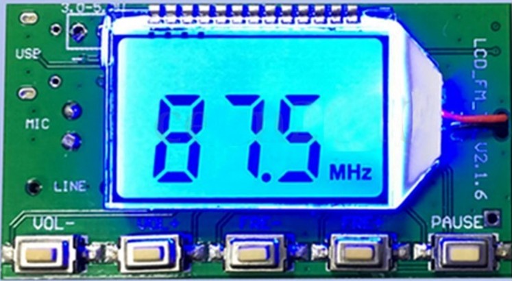
- FM Transmitter
- The stereo output from the music player goes to the low power (100 mW) FM transmitter.
The Display broadcasts music on FM 89.3 MHz; the range is about 1 block.
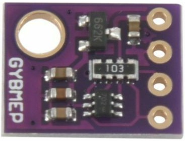
- Weather Station
- The Display includes a BME280 temperature, humidity and barometric pressure sensor.
The information from the sensors is included on the Live web page available to users.
CUSTOM DISPLAYS
These are the things you see lighting up in the yard - mostly custom built, some one-of-a kind.
A few of the displays are pre-built, but custom packaging helped them to integrate
effectively into the Display.
- Megatrees
- There are four Megatrees; each is 10 feet tall and 4 feet diameter at the base.
Eight strings are arranged in a circle around each tree, permitting a solidly lit tree shape or
adding animation by lighting light strings in various sequence.
Instructions for how the Megatrees were built are here.
- Red/White/Green Trees
- A row of 12 LED trees are mounted on a wooden frame in front of the Megatrees.
Each tree is x inches wide and x inches high; the three colors of each tree may be independently lit,
permitting animation in sync with the music being played.
- Fallen Arches
- A row of 12 upside down arches are mounted on a wooden fram in front of the R/W/G trees.
Each arch is x inches wide and x inches tall.
Only red and green incadescent lights are contained in the Fallen Arches, and each color of each arch
can be indidually lit.
- Warm White Trees
- A row of 8 LED trees are mounted on a welded wire fence frame on the left side of the display.
Each tree is x inches wide and x inches tall.
Each tree can be lit individually.
Instructions for how the trees were built are here
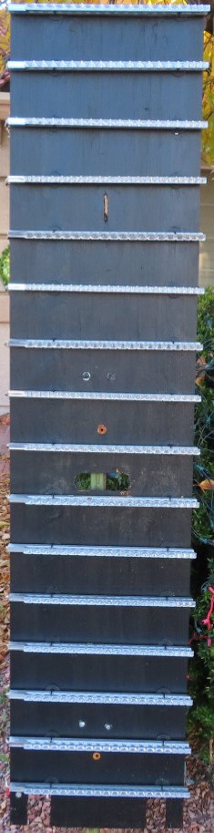
- VU Meter
- The Display contains a custom-built Volume Unit Meter (VUmeter) that activates up to 16
vertical LED bars based on music volume.
The display is large, 16 inches wide and 6 feet tall.
- Lighted Packages
- While not a custom display, the lighted Christmas packages on the garage door were made possible by
carefully selecting the position of the display so that it did not interfere with the opening/closing of the garage door.
Likewise, the power cord to the display was positioned so that it will not get tangled in the packages or the
garage door panels.
- Sequencing Lights
- Doors and windows are framed by lights that can be sequenced to provide animation to the display.
Three strings of lights are zip-tied together with individual bulbs in sequence from string 1-2-3-1-2-3-1-2-3-etc.
When the light strings are turned-on in sequence they give the appearance of motion around the frames.
- Servo Controlled Lights
- On the right side of the display above the USA flag, red and white lights are mounted on Servos
that pan the lights up/down and left/right.
While the servos function as intended and this seemed like a good idea at the time, the lights don't show off
very well because some sort of mist or "fog" needs to be present to achieve the desired effect.
Oh, well ... it was an interesting challenge to get the servos to operate correctly!
- Tune To FM 89.3
- These signs were made by coordinating digitized text characters with the number of bulbs available in
the incandescent llght strings that were on hand.
Holes are simply drilled in a thin masonite board, and the bulbs inserted to provide a colorful image.
- Brinkman.Christmas sign
- The sign needed to be highlighted to visitors, but illuminated in such a way that
the lights did not shine directly into their eyes.
The solution was to implement a "shadow box" design recessed 4 inches into a frame, with a wide
front lip that permitted mounting strips of LED lights facing inward to the sign.
PROTOTYPING, TESTING and MONITORING
Electrical circuits can consist of thousands of connections.
During early development subsections of the final project are often developed in building blocks
because the whole project can get to be unmanageable.
- Breadboards
- Development projects usually start off with prototype breadboards and jumper wires
that permit easy connection, reconfiguration and reconnection.
Breadboards are often fragile because the push-in wires can wiggle, giving intermittent connections.
But they serve their purpose by making it easy to tweak things until the bugs are worked out.
Here's several breadboards from the original Arduino Mega 2560 implementation
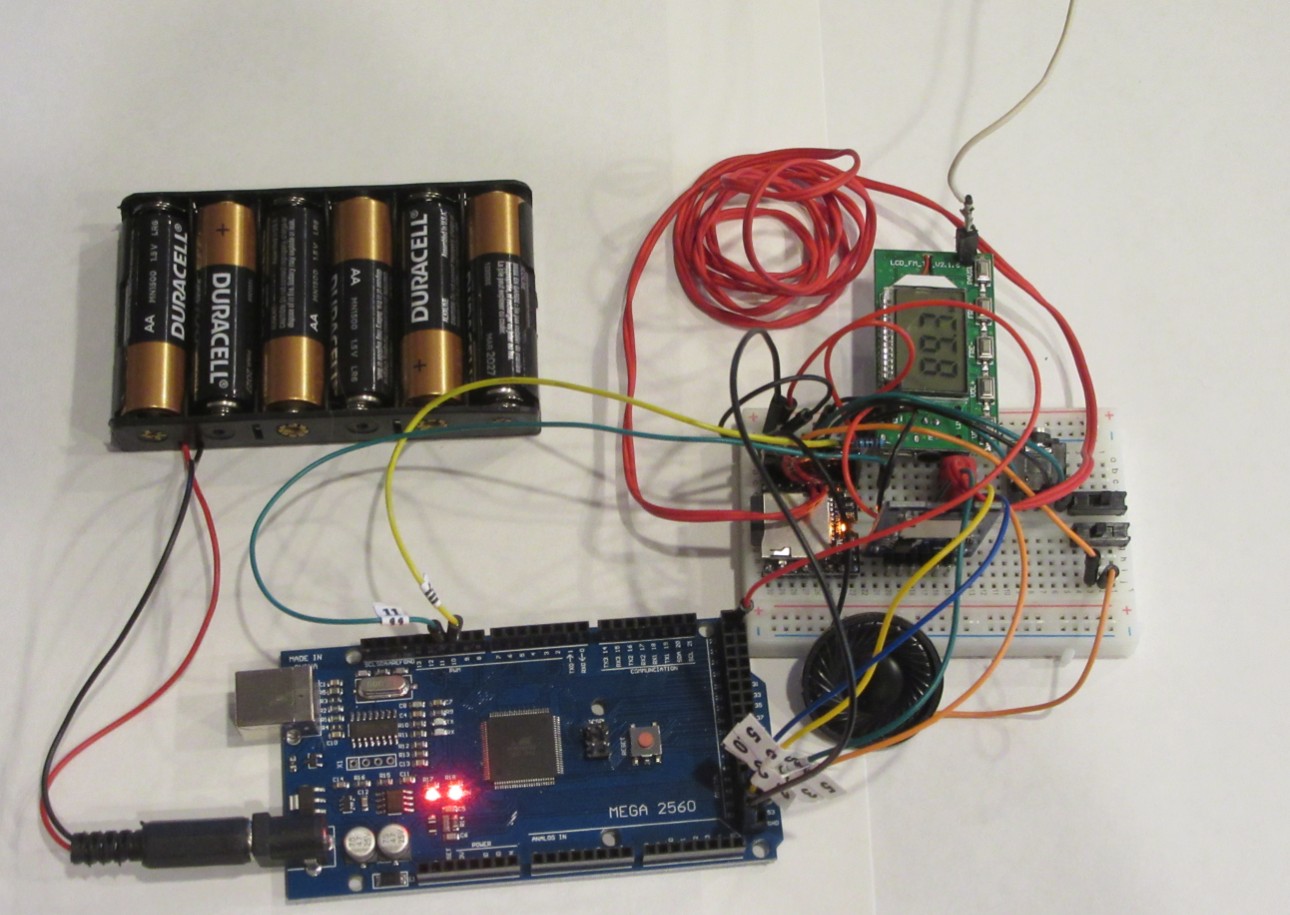
Music player/FM transmitter
|
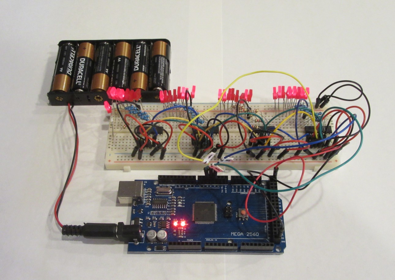
Shift registers/LEDs
|
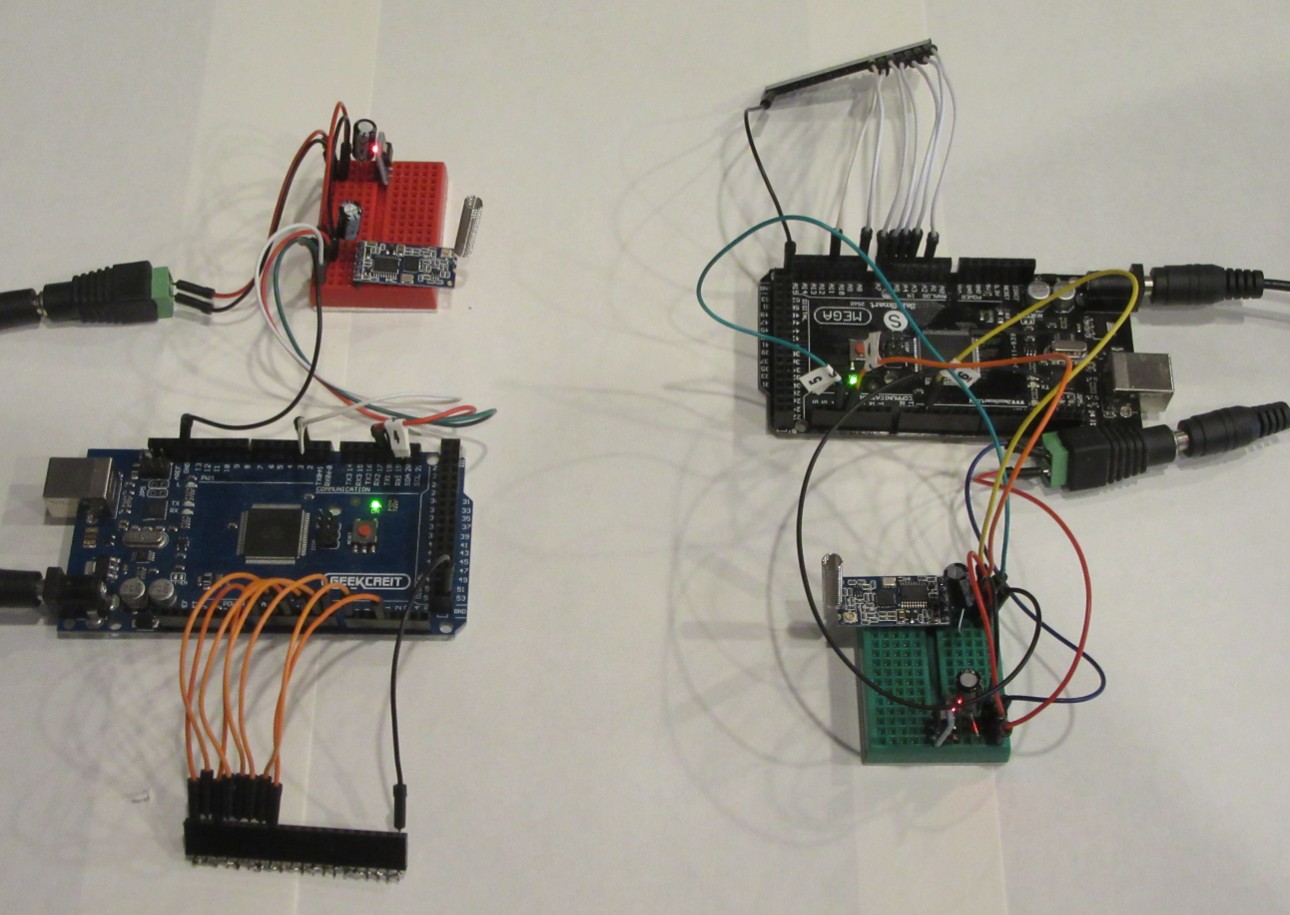
Wireless communication between units
|
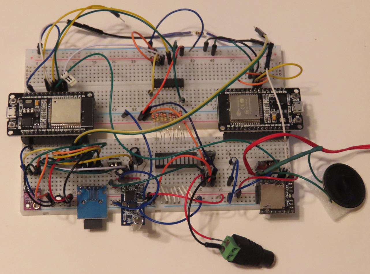
Here's the breadboard for the ESP32-based design.
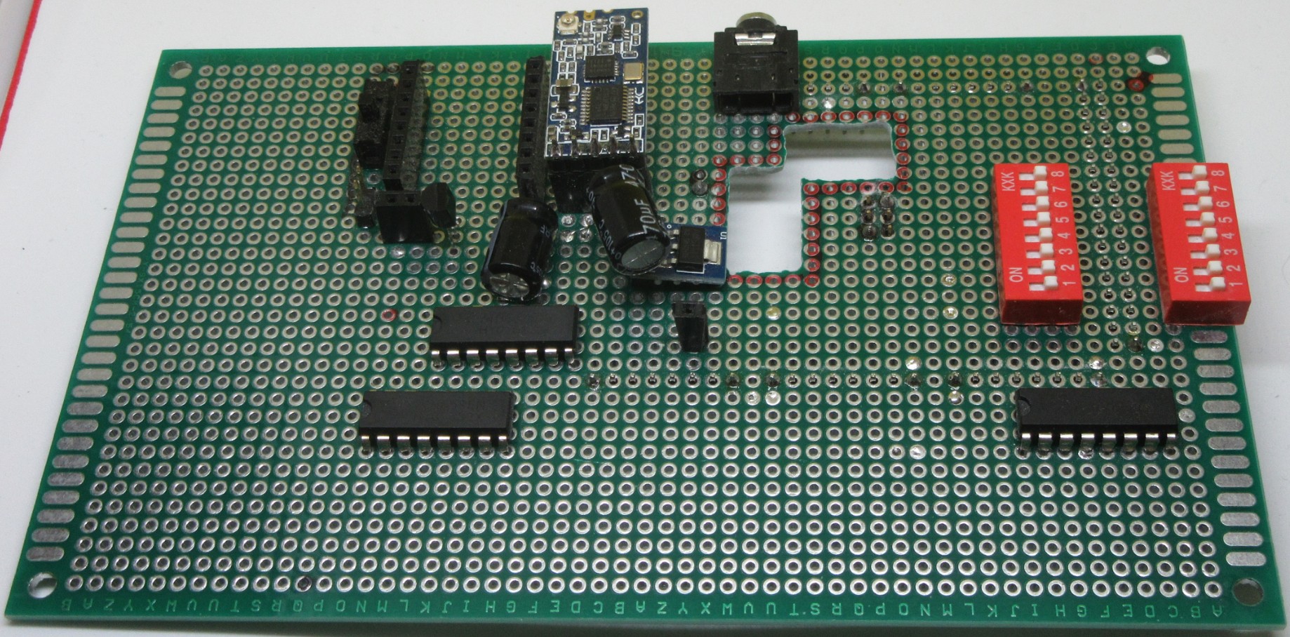
- Brassboards
- A next step is to visualize where all the components will be placed,
to check for clearances between parts, feasibility of plugging in cables,
and to check for accessibility of things like switches and microSD
cards that will need to be mounted/unmouinted.
Here's a partially completed brassboard for the Mega/ESP8266 design.
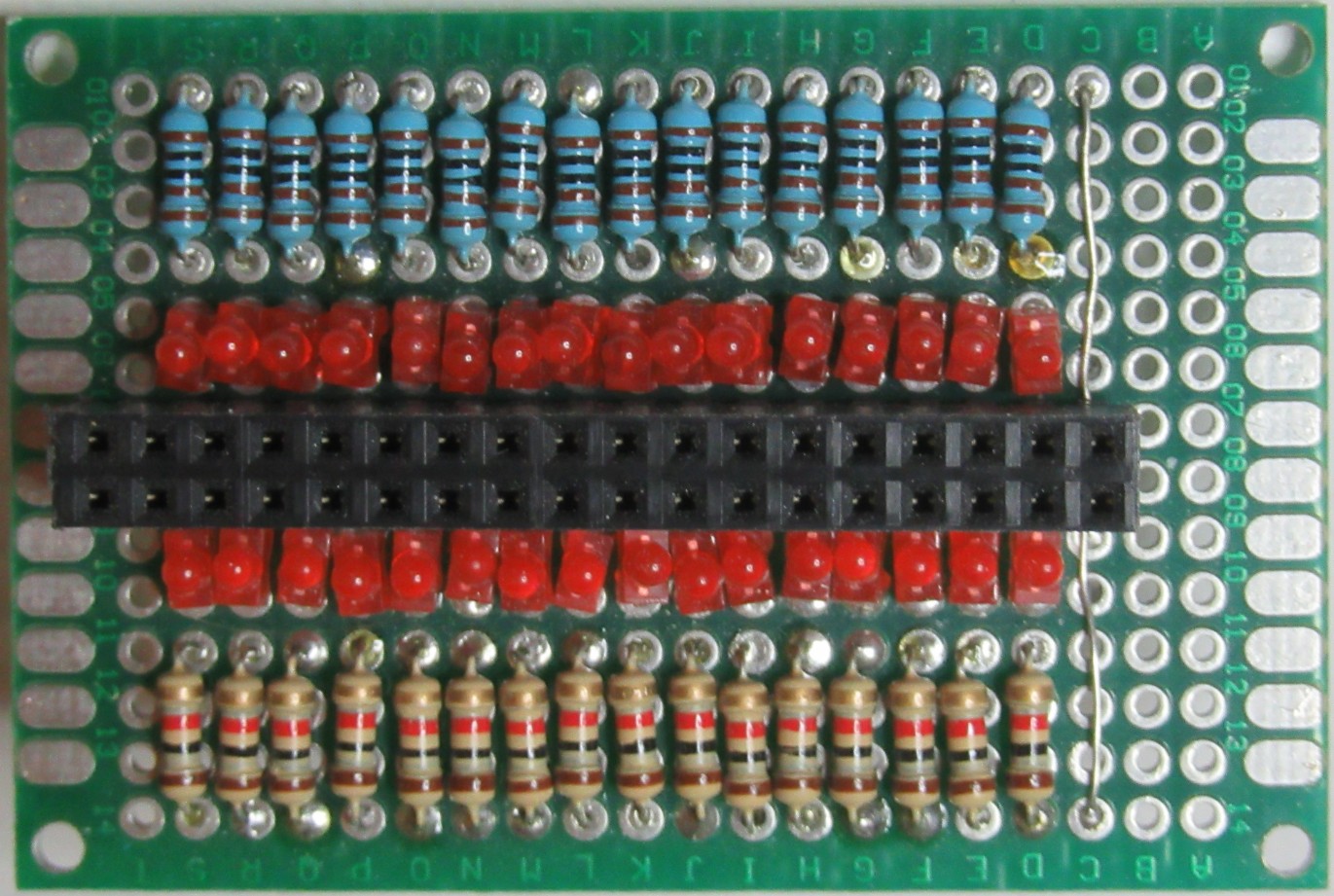
- Fixtures
- Fixtures are very useful during various stages of electrical and mechanical construction.
They can be fairly crude - just as long as they are useful to help manage the development or
construction task at hand.
This fixture plugs into the Mega's digital output pins and illuminates a LED if that output goes
to a HIGH or ON state.
This fixure was used to help mount lights on the Servos uniformly.

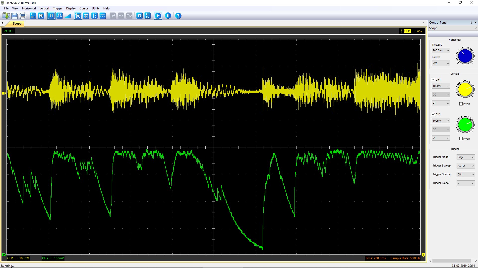
- Oscilloscope
- When developing the VUmeter I had to check the input (analog) audio signal and compare
it with the output signal that was amplified and filtered to give the desired effect.
The graphical output was priceless in configuring the circuit correctly.
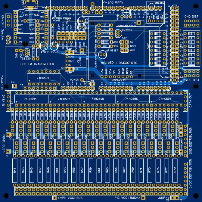
- Printed Circuit Board (PCB)
- The final design is implemented by a PCB.
PCBs provide an easy way to manage all the thousands of connections, especially when dealing with
many very small components.
The PCB design is started by composing a Schematic Diagram.
Then each component is carefully laid out where you want it, and an automated tool figures
out all the needed wiring interconnections.
The tool generates files that automated machines use to manufacture the PCBs.
- Light Testing
- During development as well as after deployment in your yard, things will go wrong.
It's handy, therefore, to have a testing capability as a troubleshooting aid.
A hidden web page permits the following light tests:
- Turn on one or more banks of lights (8 lights per bank).
This is handy for checking for burned-out light bulbs.
- Sequence all banks of lights.
In sequence, turn on light 1-2-3-4-5-6-7-8-OFF, then repeat.
This is handy for checking wiring and verifying that the right light is plugged into the right socket.
- Normal Operation.
When testing is done, return the system to normal operation.
- Monitoring
- Error Checking
- Each Light Command transmitted by the Master unit contains an error check byte
with the data that is transmitted.
The Slave units check the byte, and if a Light Command has been missed they log the incident.
When queried for a Health report each Slave unit reports the number of errors encountered.
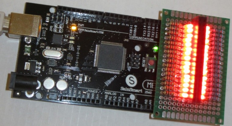
- Office Monitor
- A Slave unit permanently resides in my office that can be configured to monitor
a choice of five banks of lights on a strip of 40 bar LED lights.
During operation of the Display the lights in my office activate along with the actual Display.
I can easily glance over to confirm that activity is happening outside.
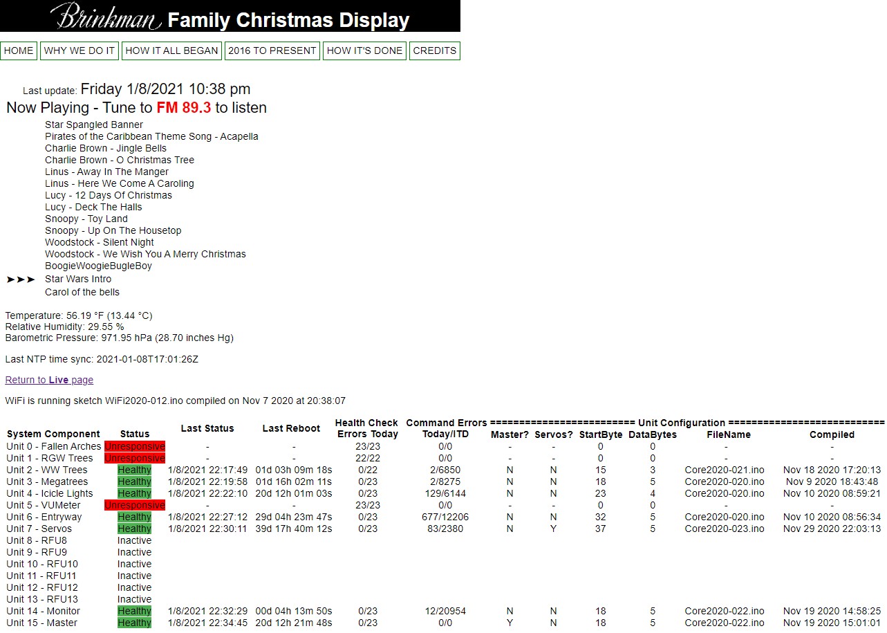
- Health Check
- Another hidden web page shows the result of querying the health of all the units
in the Display.
At glance I can see how things are working.
A few notes about the sample Health Check page below:
- Three of the units are receiving data fine, but for some reason are not responding to Health
Check requests.
I'll addresss that sometime in the future; in the meantime the light displays for the units
are working :-)
- It is normal to have errors - you just don't want too many errors.
Power line spikes, lightning or other electrical noise can cause a transmitted
Light Command to be missed.
When the next vaild packet arrives (usually in just a few milliseconds) the light display
for that unit resumes correctly.
- As shown, the last time status was reported, the last time the unit rebooted, and software
version loaded in the unit is reported.
The report permits checking up on the system without having to go outside to look at it.
.
.
.
 Family Christmas Display